 EN
EN
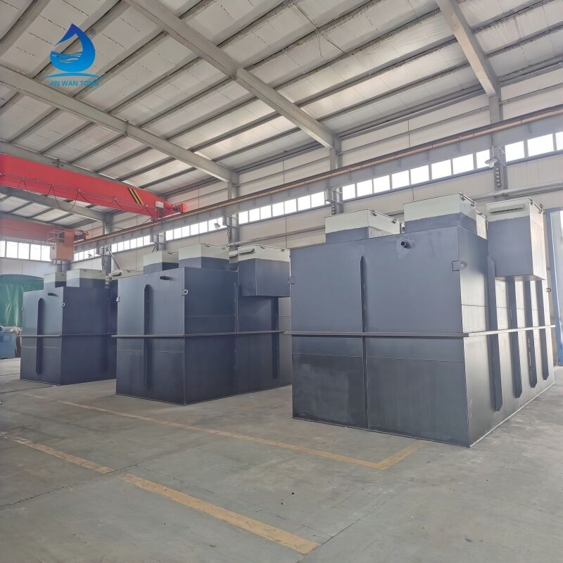
Understanding how a CPI filter integrates into a complete oil-water separation system is essential for industries managing contaminated wastewater streams containing free and emulsified oils. The CPI filter, which stands for Corrugated Plate Interceptor filter, operates as a critical component within multi-stage treatment systems designed to separate hydrocarbons from process water efficiently. This integration is not a standalone process but rather a carefully coordinated sequence of pre-treatment, separation, and post-treatment stages that work together to achieve regulatory discharge standards. The CPI filter specifically targets the removal of suspended oil droplets and particulate matter after initial gravity separation has removed the bulk of free-floating oils, making it an intermediary yet indispensable element in the treatment chain.
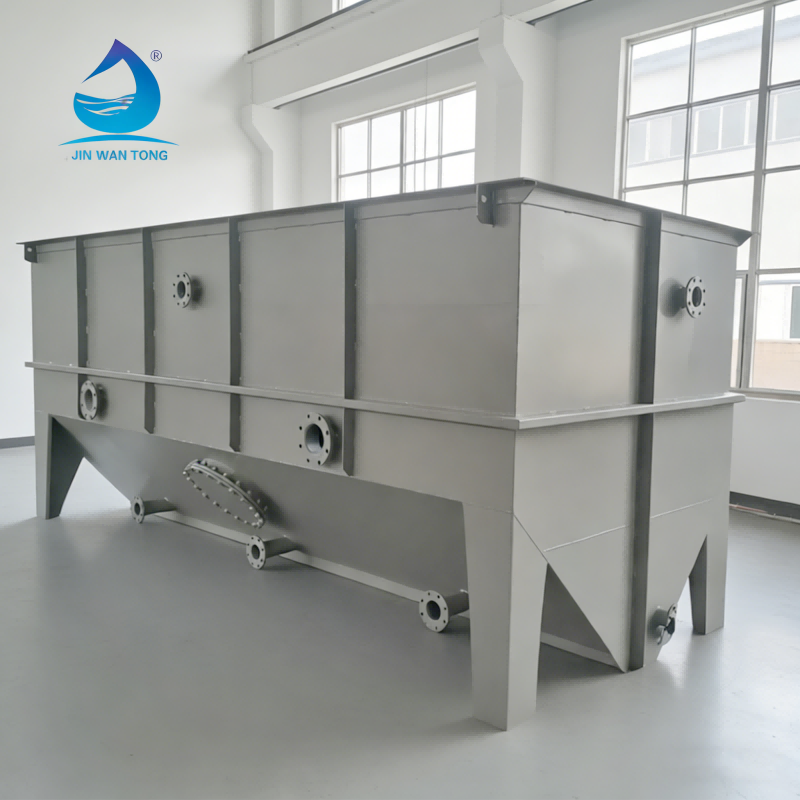
The integration process involves hydraulic coordination, structural positioning, and operational sequencing that must account for flow rates, oil droplet sizes, chemical properties of contaminants, and downstream treatment requirements. A properly integrated CPI filter receives pre-conditioned wastewater that has already passed through screens and API separators, then delivers effluent with significantly reduced oil content to downstream polishing units such as dissolved air flotation systems or multimedia filters. This article explores the mechanical, hydraulic, and operational principles that govern how a CPI filter functions within the broader architecture of industrial oil-water separation systems, providing technical insights for engineers and facility managers responsible for wastewater treatment design and compliance.
System Architecture and Component Positioning
Upstream Pre-Treatment Requirements Before CPI Filter Integration
Before wastewater enters the CPI filter, it must undergo primary treatment to remove large solids and free oils that could compromise filter performance. This pre-treatment typically begins with bar screens or basket strainers that capture debris larger than five millimeters, preventing mechanical damage to downstream equipment. Following solids removal, the flow enters an equalization tank where hydraulic surges are dampened and flow rates are stabilized, ensuring the CPI filter receives a consistent influent volume that matches its design capacity. This equalization phase is critical because sudden flow variations can disturb the laminar flow patterns required for effective oil droplet coalescence within the corrugated plate media.
The next pre-treatment stage usually involves an API separator or similar gravity-based unit that removes free oils with droplet diameters typically above 150 microns. This primary separation reduces the oil load entering the CPI filter by approximately sixty to eighty percent, allowing the CPI filter to focus on smaller droplets that resist simple gravity separation. Temperature conditioning may also occur at this stage, as oil viscosity and specific gravity are temperature-dependent properties that directly affect separation efficiency. Wastewater temperatures are often maintained between twenty and thirty-five degrees Celsius to optimize the density differential between oil and water phases.
Physical Placement and Hydraulic Connections
The CPI filter is typically installed immediately downstream of the primary gravity separator, often at an elevation that allows gravity flow between units to minimize pumping costs and energy consumption. The physical footprint must accommodate inlet distribution chambers that ensure uniform flow distribution across the corrugated plate pack, as uneven flow creates preferential pathways that reduce contact time and separation efficiency. Inlet chambers often incorporate baffles or perforated distribution walls that dissipate inlet momentum and convert turbulent flow into the laminar conditions necessary for droplet coalescence.
Hydraulic connections between the API separator and the CPI filter must maintain continuous liquid levels to prevent air entrainment, which can re-emulsify separated oils and defeat the separation purpose. Piping diameters are sized to maintain flow velocities below 0.3 meters per second, preventing turbulence that would break up coalesced oil droplets. Isolation valves and bypass piping are integrated into the connection design to allow maintenance of the CPI filter without shutting down the entire treatment system, providing operational flexibility during cleaning cycles or equipment repairs.
Integration with Control and Monitoring Infrastructure
Modern CPI filter installations include instrumentation that monitors differential pressure, flow rates, and effluent oil content, with signals transmitted to a centralized programmable logic controller or distributed control system. These monitoring points enable operators to detect fouling conditions, optimize backwash cycles, and verify compliance with discharge permits. Level sensors in the oil collection chamber trigger automated skimming systems that remove concentrated oils without manual intervention, improving operational consistency and reducing labor requirements.
The control system coordinates the operation of the CPI filter with upstream and downstream equipment, adjusting flow rates and initiating cleaning sequences based on real-time performance data. This integration extends to chemical dosing systems that may inject coagulants or flocculants upstream of the CPI filter to enhance droplet agglomeration, and to pH adjustment systems that optimize the surface charge characteristics of oil droplets to promote coalescence. Alarm systems alert operators to abnormal conditions such as excessive pressure drop or elevated effluent oil concentrations, enabling rapid response to prevent permit violations.
Hydraulic and Process Flow Dynamics
Flow Distribution and Laminar Flow Establishment
Achieving effective oil-water separation within a CPI filter depends fundamentally on establishing laminar flow conditions through the corrugated plate channels, where Reynolds numbers typically remain below 500 to prevent turbulence that disrupts droplet coalescence. The inlet distribution system must transform the incoming flow from potentially turbulent conditions into a uniform velocity profile across the entire width of the plate pack. This transformation occurs through a combination of expansion chambers, flow straighteners, and perforated distribution plates that break down large-scale turbulence into manageable velocity gradients.
The corrugated plates themselves, typically oriented at angles between forty-five and sixty degrees from horizontal, create parallel flow channels with hydraulic diameters ranging from ten to thirty millimeters. These narrow channels impose a velocity constraint that naturally promotes laminar conditions even at relatively high volumetric flow rates. The plate spacing and angle are engineered to balance two competing objectives: maximizing surface area for droplet capture while maintaining sufficient channel velocity to prevent solids deposition that could blind the filter media over time.
Oil Droplet Capture Mechanisms Within CPI Filter Media
As wastewater flows through the corrugated channels, oil droplets migrate toward the upper surface of each plate through a combination of buoyancy and interception. Droplets smaller than fifty microns follow fluid streamlines closely but gradually drift upward due to their lower density compared to water, eventually contacting the plate surface where they adhere and coalesce with other captured droplets. Larger droplets, typically in the range of seventy-five to two hundred microns, exhibit greater buoyancy-driven rise velocities and intercept the plate surface more quickly, often within the first third of the plate length.
Once captured on the plate surface, small droplets merge into larger coalescent masses through surface tension forces, forming films that creep along the underside of the corrugated peaks. These oil films accumulate at collection troughs positioned at the downstream end of the plate pack, where they are directed to an oil chamber for removal by skimming systems. The efficiency of this capture process depends critically on maintaining the proper flow velocity through the channels—too fast and droplets lack sufficient residence time for interception, too slow and solids begin to settle and foul the plate surfaces.
Residence Time Calculation and System Sizing
Engineers determine the required CPI filter size by calculating the minimum residence time needed for target oil droplet sizes to rise from the bottom to the top of the flow channel under laminar conditions. Stokes' Law provides the theoretical foundation for these calculations, relating droplet rise velocity to droplet diameter, density differential, and fluid viscosity. For typical refinery wastewater applications targeting removal of sixty-micron droplets, residence times of fifteen to thirty minutes within the CPI filter are common, translating to plate pack dimensions that provide adequate surface area and flow path length.
System integration must ensure that the actual flow rate through the CPI filter matches the design rate, as even modest flow increases can reduce residence time below the critical threshold and cause breakthrough of target droplet sizes. Flow equalization tanks upstream of the CPI filter serve this purpose, absorbing peak flow periods and releasing water at a controlled rate. Automated flow control valves maintain setpoint flow rates regardless of upstream variations, protecting the separation performance from hydraulic overload conditions that would otherwise compromise effluent quality.
Downstream Treatment Chain and Effluent Polishing
Secondary Treatment Stage Integration
The effluent discharged from a CPI filter typically contains residual oil concentrations between ten and fifty milligrams per liter, consisting primarily of emulsified oils and fine droplets that resist gravity-based separation. This partially treated water requires additional polishing to meet discharge limits that commonly range from five to fifteen milligrams per liter for total petroleum hydrocarbons. The integration strategy must therefore incorporate downstream treatment technologies capable of addressing these persistent contaminants without creating operational bottlenecks or excessive treatment costs.
Dissolved air flotation units represent the most common secondary treatment following CPI filter systems, particularly in applications where emulsified oils and suspended solids dominate the remaining contaminant load. The CPI filter effluent feeds directly into the flotation cell reaction zone where microscopic air bubbles attach to oil droplets and particles, forming buoyant aggregates that float to the surface for mechanical removal. This pairing of CPI filter and flotation technologies creates a synergistic treatment train where each unit addresses different droplet size ranges—the CPI filter handles free oils above twenty microns while flotation targets emulsified oils below twenty microns.
Multimedia Filtration as Tertiary Polishing
For applications requiring extremely low effluent oil concentrations below five milligrams per liter, multimedia filters often follow the CPI filter or flotation unit as a tertiary treatment stage. These filters employ beds of graded anthracite, sand, and garnet that capture residual oil droplets and particulate matter through depth filtration mechanisms. The integration point between the CPI filter system and multimedia filters requires careful attention to suspended solids loading, as excessive solids can rapidly exhaust the filter capacity and necessitate frequent backwashing that increases operational costs and water consumption.
Effluent from the CPI filter typically exhibits suspended solids concentrations suitable for direct multimedia filtration without intermediate clarification, provided the upstream pre-treatment adequately removed bulk solids. However, if the CPI filter effluent contains elevated solids due to upstream process upsets or inadequate maintenance, a settling basin or lamella clarifier may be inserted between the CPI filter and multimedia filters to prevent premature filter fouling. This contingency integration demonstrates the importance of designing flexible treatment systems that can accommodate process variations without compromising final effluent quality.
Final Discharge and Compliance Monitoring
The complete oil-water separation system culminates in a final monitoring station where continuous analyzers measure oil content, pH, temperature, and other parameters specified in discharge permits before release to receiving waters or municipal sewers. The CPI filter contribution to overall system performance is quantified at this point through comparison of influent and effluent oil concentrations, with properly integrated systems demonstrating removal efficiencies exceeding ninety-five percent when all stages operate within design parameters. Automated sampling systems collect representative samples for laboratory analysis to verify compliance with permit limits and document treatment system effectiveness.
Integration with discharge infrastructure includes provisions for flow measurement, emergency retention capacity, and fail-safe diversion to holding tanks if effluent quality excursions occur. The CPI filter operation directly impacts these final discharge capabilities, as breakthrough conditions in the filter can overwhelm downstream polishing units and threaten permit compliance. Monitoring systems therefore include early warning indicators tied to CPI filter performance, such as differential pressure trends and oil layer thickness in the collection chamber, enabling operators to intervene before effluent quality deteriorates to non-compliant levels.
Operational Integration and Maintenance Protocols
Cleaning Cycles and Backwash Integration
Maintaining optimal CPI filter performance within an integrated treatment system requires periodic cleaning to remove accumulated solids and biological growth from the corrugated plate surfaces. These cleaning cycles must be coordinated with system-wide operations to prevent process disruptions and maintain continuous treatment capacity. Most installations employ redundant CPI filter trains that allow one unit to undergo cleaning while the other handles the full flow, or incorporate bypass provisions that temporarily route flow around the CPI filter to downstream units with sufficient capacity to manage the increased load.
The cleaning process typically involves draining the CPI filter, applying pressurized water sprays or chemical cleaning solutions to the plate pack, and flushing accumulated debris to waste. Integration considerations include providing adequate drainage capacity for cleaning effluent, which may contain concentrated oils and solids requiring separate disposal or recirculation through the head of the treatment train. Chemical cleaning systems must be integrated with safety interlocks that prevent operator exposure to hazardous cleaning agents and ensure complete rinsing before the CPI filter returns to service.
Oil Recovery and Waste Management Integration
The concentrated oil recovered from the CPI filter collection chamber represents a valuable byproduct that can be recycled or disposed of depending on its quality and contamination level. Integration with oil recovery infrastructure typically includes automated skimming systems that continuously remove floating oil layers and transfer them to storage tanks for subsequent processing. The recovery rate must balance conflicting objectives: frequent skimming minimizes the oil layer thickness and reduces the risk of re-entrainment, but may recover oil with higher water content that requires additional dewatering before reuse or disposal.
Waste solids removed during CPI filter cleaning and maintenance must be managed through integrated handling systems that may include dewatering equipment, containerized storage, and licensed disposal services for hazardous waste if contaminants exceed regulatory thresholds. The integration design allocates space for temporary waste storage, provides containment to prevent environmental releases, and ensures compatibility between waste characteristics and disposal methods. These waste management provisions directly impact the overall system footprint and operating costs, requiring consideration during the initial integration planning phase.
Performance Optimization Through Process Control
Advanced integration strategies employ real-time process control algorithms that continuously optimize CPI filter operation based on influent characteristics, effluent quality targets, and downstream treatment capacity. These control systems may automatically adjust flow rates through the CPI filter in response to changes in influent oil concentration, reducing flow during high-loading periods to maintain adequate residence time and increasing flow when influent quality improves to maximize system throughput. Such dynamic optimization requires sophisticated instrumentation and control architecture that extends across the entire treatment system, not just the CPI filter itself.
Integration with upstream chemical dosing systems enables feed-forward control strategies where coagulant or polymer addition rates are adjusted based on real-time measurements of influent oil content and droplet size distribution. This proactive approach enhances the CPI filter separation efficiency by conditioning the wastewater before it enters the corrugated plate pack, promoting faster coalescence and more complete oil removal. The control system must balance chemical costs against improved performance, seeking the optimal dosing rate that achieves effluent targets at minimum expense.
Design Considerations for Effective System Integration
Capacity Planning and Hydraulic Balancing
Successful integration of a CPI filter into a complete oil-water separation system begins with comprehensive capacity planning that accounts for peak flow conditions, seasonal variations, and potential future expansion requirements. The CPI filter must be sized not only for average flow rates but also for the maximum instantaneous flow it may encounter, incorporating safety factors that prevent hydraulic overload during upset conditions. This sizing philosophy extends to all system components, ensuring that bottlenecks do not develop at any point in the treatment chain that could force bypassing of critical treatment stages.
Hydraulic balancing across the integrated system requires analysis of pressure profiles from the inlet to the final discharge point, accounting for elevation changes, friction losses, and head requirements for each treatment unit. The CPI filter typically operates under gravity flow conditions with minimal pressure drop, but the overall system may require booster pumps at strategic locations to overcome elevation differences or deliver adequate pressure to downstream equipment. These pumping stations must be integrated with level controls that prevent cavitation, deadheading, or overflow conditions that could damage equipment or compromise treatment performance.
Material Selection and Corrosion Management
The integration environment for a CPI filter often involves exposure to corrosive wastewater constituents including dissolved salts, organic acids, and hydrogen sulfide that can degrade metal components over time. Material selection for the CPI filter structure, piping connections, and ancillary equipment must consider both the chemical characteristics of the wastewater and the long-term durability requirements of continuous industrial service. Stainless steel grades such as 316L provide excellent corrosion resistance for most applications, while fiberglass-reinforced plastic offers a cost-effective alternative for less demanding conditions.
Galvanic corrosion risks arise when dissimilar metals are joined in the integrated system, requiring careful attention to material compatibility at connection points between the CPI filter and adjacent equipment. Dielectric unions, isolation gaskets, and sacrificial anodes may be incorporated into the integration design to prevent accelerated corrosion at these vulnerable locations. The long-term maintenance burden and replacement costs for corroded components can significantly impact the total cost of ownership, making corrosion management a critical aspect of the integration planning process.
Footprint Optimization and Site Layout
Industrial facilities face increasing pressure to minimize the land area dedicated to wastewater treatment infrastructure, driving integration strategies that optimize the spatial arrangement of treatment units while maintaining operational accessibility and safety clearances. The CPI filter can be integrated into compact treatment systems through vertical stacking arrangements, where the unit is elevated above the primary separator and discharges by gravity to downstream equipment below. This three-dimensional approach reduces the overall system footprint but complicates construction and may increase structural support costs for elevated equipment.
Site layout integration must also accommodate access requirements for maintenance activities, including crane paths for plate pack removal, clearances for pressure washing equipment, and storage areas for cleaning chemicals and replacement parts. The layout should facilitate logical process flow with minimal crossovers and backtracking of piping, reducing construction costs and simplifying system operation. Environmental considerations such as odor control, noise mitigation, and visual screening may influence the positioning of the CPI filter relative to property boundaries and occupied buildings, requiring integration of enclosures or landscaping features that address these concerns.
FAQ
What is the typical oil removal efficiency achieved when a CPI filter operates within an integrated treatment system?
A properly integrated CPI filter typically achieves oil removal efficiencies between eighty-five and ninety-five percent for free and dispersed oils with droplet sizes above twenty microns, reducing influent concentrations from several hundred milligrams per liter down to ten to fifty milligrams per liter in the effluent. The actual efficiency depends on influent characteristics, upstream pre-treatment effectiveness, flow rate consistency, and maintenance practices. When combined with upstream API separation and downstream flotation or filtration, the complete system can achieve overall removal efficiencies exceeding ninety-eight percent, producing final effluent with oil concentrations below five milligrams per liter suitable for discharge or reuse applications.
How does temperature affect the integration and performance of a CPI filter in oil-water separation systems?
Temperature significantly influences both oil and water properties that govern separation performance in a CPI filter, with optimal operation typically occurring between twenty and thirty-five degrees Celsius. Higher temperatures reduce oil viscosity and increase the density differential between oil and water phases, enhancing droplet rise velocity and improving separation efficiency. However, temperatures above forty degrees Celsius can promote biological growth on plate surfaces and may require materials rated for elevated temperature service. Integration strategies for temperature-sensitive applications include heat exchangers positioned upstream of the CPI filter to maintain optimal operating temperature regardless of influent variations, and insulation systems that prevent heat loss in cold climates where freezing could damage equipment.
What upstream pre-treatment is essential before wastewater enters a CPI filter?
Essential pre-treatment before a CPI filter includes coarse screening to remove debris larger than five millimeters that could damage or clog the corrugated plate pack, followed by primary gravity separation in an API separator or similar unit to remove free oils with droplet diameters above one hundred fifty microns. Flow equalization is also critical to dampen hydraulic surges and deliver consistent flow rates that match the CPI filter design capacity. Additional pre-treatment such as pH adjustment, temperature conditioning, or chemical coagulant addition may be integrated depending on specific wastewater characteristics and treatment objectives, ensuring the CPI filter receives influent conditioned for optimal separation performance and long service life between maintenance intervals.
Can a CPI filter operate effectively as a standalone treatment unit without additional downstream polishing?
While a CPI filter can function as a standalone unit for applications with lenient discharge requirements or where residual oil concentrations of ten to fifty milligrams per liter are acceptable, most regulatory frameworks and industrial reuse applications demand more stringent final effluent quality that necessitates downstream polishing treatment. The CPI filter excels at removing free and dispersed oils but cannot effectively address emulsified oils, dissolved hydrocarbons, or fine particulate matter that persist in the effluent. Effective integration therefore typically includes downstream technologies such as dissolved air flotation, multimedia filtration, activated carbon adsorption, or membrane separation to achieve final effluent quality below five to fifteen milligrams per liter total petroleum hydrocarbons, ensuring compliance with environmental permits and enabling beneficial reuse of treated water.
Table of Contents
- System Architecture and Component Positioning
- Hydraulic and Process Flow Dynamics
- Downstream Treatment Chain and Effluent Polishing
- Operational Integration and Maintenance Protocols
- Design Considerations for Effective System Integration
-
FAQ
- What is the typical oil removal efficiency achieved when a CPI filter operates within an integrated treatment system?
- How does temperature affect the integration and performance of a CPI filter in oil-water separation systems?
- What upstream pre-treatment is essential before wastewater enters a CPI filter?
- Can a CPI filter operate effectively as a standalone treatment unit without additional downstream polishing?